To understand the ECML problem we need some technical background. Stick with me and I’ll make this as painless as possible.
1. THREE-PHASE DRIVE
In the beginning was the diode. This solid-state power device allowed AC to flow one way but blocked it in reverse. It was a rectifier, replacing tanks full of mercury into which an electrode struck a spark. Yes, that is how the first AC locomotives supplied their direct current (DC) traction motors.
Then came the thyristor, which could be switched on during the forward half of the sine wave but still blocked reverse current automatically when the sine wave passed through zero. By varying the point at which the thyristor switched ‘on’ during the conducting phase, you could control the power.
Then came the Gate Turn Off thyristor (GTO), which, no surprise, could be turned on and off. This allowed traction engineers to devise all sorts of clever control schemes such as DC ‘choppers’ and three-phase drive.
Today, we have the Integrated Gate Bi-polar Transistor (IGBT), which has been around since the mid-1990s. These have lower losses and switch on and off faster, allowing even cleverer drives, which is a good thing if you are a traction engineer.
2. EMC
However, it is not so good if you are a signalling engineer. All this switching current on and off to provide the Variable Voltage/ Variable Frequency (VVVF) supply needed by three-phase drive motors creates a spectrum of frequencies in the return current going to earth via the running rails.
Also in the running rails, there may be electric currents used for signalling track circuits. These may be at a particular frequency aimed at avoiding harmonic frequencies in the traction return currents.
Three-phase drives generate a wide spectrum of frequencies. At the heart of the safety case wars, where the Class 323 was the first to emerge triumphant, was the use of switching strategies to avoid producing frequencies that would cause a track circuit failure.

As a back-stop there was the dreaded ICMU – Interference Current Monitoring Unit – which would shut down the drive if it detected a critical frequency in the output. As a diversion, the first time the Class 323s encountered rime-covered contact wires, the arcing and sparking at the pantograph generated the electric version of white noise. The ICMU saw every forbidden frequency and shut down the train.
As a further diversion, the ICMU is still with us. On a couple of occasions a Class 800 bowling happily along under the GWML wires has been detected producing forbidden frequencies and switched to diesel mode.
Axle counters are largely replacing track circuits. There are track circuits that use clever coding in the electric signal to make them Traction Immune.
3. INDUCTION
If you have two wires side by side, an alternating current in one will create a magnetic flux which, through inductive coupling, will generate a current in the second wire. If we think of the running rails as a very thick wire, the return current in the rail from a passing train will generate a current in any parallel lineside cable. This is known as ‘common mode’ current and will contain the same frequencies as those in the rail.
Note that common mode current is dependent on a number factors – such as the length of the lineside wires and even the resistance of the infrastructure, for example at viaducts. Fitment of booster transformers in the overhead line electrification (OHLE) can reduce the current induced in the data link by a factor of five.
4. SSI
Time to brace for an alphabet soup of abbreviations. A feature of the British Rail Research Solid State Interlocking (SSI), actually the first Computer Based Interlocking (CBI), is the way it communicates with the lineside equipment. Each set of points or signal is driven by a Trackside Functional Module (TFM).
Connecting the interlocking and the TFMs is a Trackside Data Link (TDL). This is a screened twisted pair of copper cables running along beside the track. Those clever folk at Park Signalling have developed a fibre optic TDL that is about to start a trial installation.
In operation, the interlocking sends a coded message (telegram) to each TFM in turn and the TFMs reply. A telegram is a series of rectangular electric pulses with a peak of about 5 Volts.
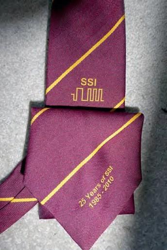
Rather than a technical drawing, the photo shows one of my favourite ties, celebrating the 25th anniversary of SSI. The symbol shows the pulses in a telegram. A pulse lasts about 3.5 thousandths of a second.
A further acronym is DLIT, for Data Link Isolation Transformers. These were fitted in long data links alongside AC electrified railways, not to protect the data transmission but to keep the voltage of the wires within safety limits if touched.
